Table of Contents
Retrofitting coaxial spdif out
This page describes how to add to a device which has already an optical spdif output a coaxial spdif output.
The modification described on this page is to add a coaxial spdif output to a Sony MDS-JE520 MiniDisc deck. Although it contains both an optical and coaxial spdif input, it only contains an optical spdif output. The lack of a coaxial spdif output is inconvenient and this modification mitigates that.
After getting hold of an RCA socket (with a shield, isolated with a plastic ring) from another SONY donor device, a hole was drilled in the back and the main circuit board was mechanically slightly modified to let the socket fit into the position where SONY originally planned a secondary optical input. The result looks like the following:
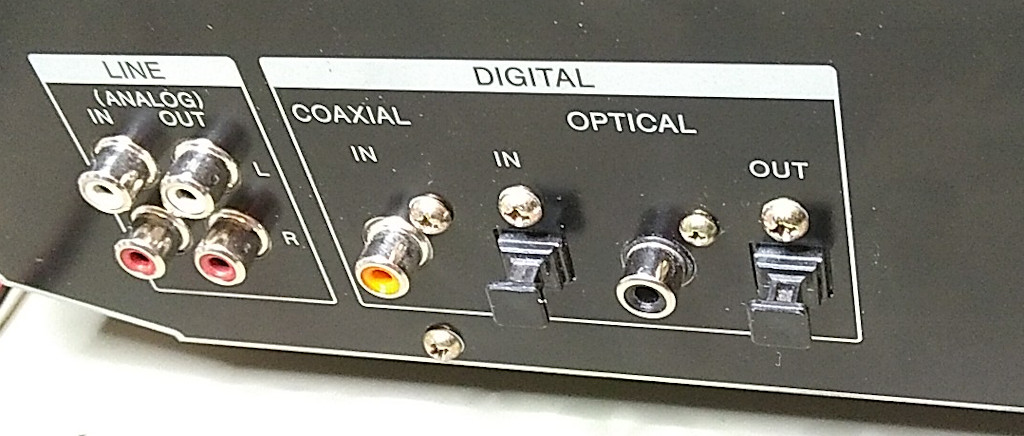 | 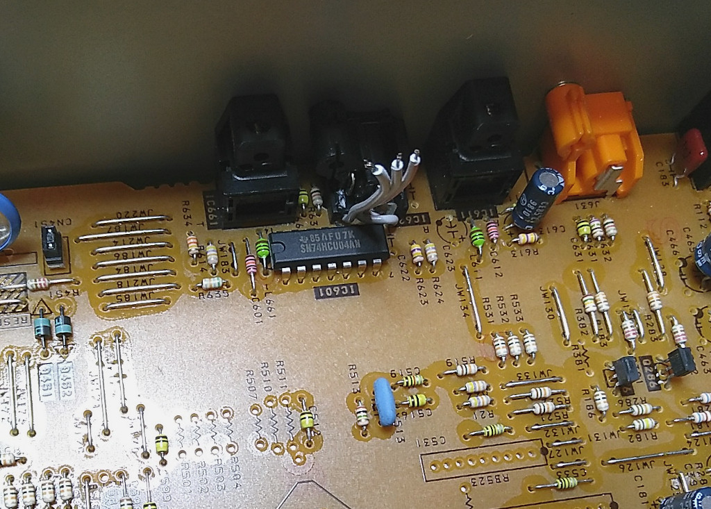 |
| Back of MDS-JE520, adding an RCA socket between optical in and out | Wires for carrying spdif signal into RCA socket1) |
Some theory: Impedance matching for a resistor voltage divider network
The complete schematic drawing of the interface is given below:
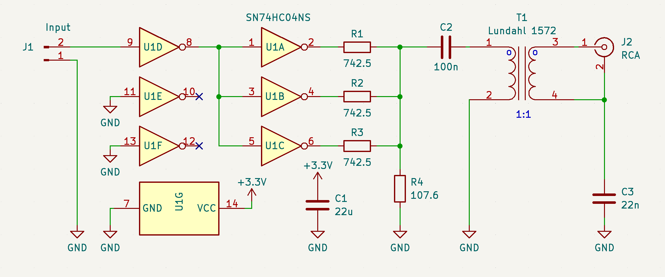 |
| Schematic of spdif coax interface |
The schematic is in essence an impedance matched voltage divider. Since the transformer (Lundahl 1572) has a 1:1 ratio, the signal is AC only and the three inverter driver outputs U1A, U1B and U1C are all identical, the schematic can be simplified for calculation.
S/PDIF signals are defined in IEC 60958-3 (2003)2). The output shall have a substantial resistive impedance of $(75\ \pm\ 15) (\Omega)$ when measured at frequencies from 0.1 MHz to 128 times the maximum frame rate, which equals to about 5.6 MHz for a sample rate of 44.1 kHz. The signal amplitude shall be $(0.5\ \pm\ 0.1 ) {\text V}$ peak-to-peak, when measured across a $(75\ \pm\ 0.75) (\Omega)$ resistor connected to the output terminals, without any interconnecting cable present.
Based on the definition above, we have two considerations to take into account: (1) Adapt the output voltage to match 0.5 v and (2) make sure the output impedance matches $75\ \Omega$. But since the output level is specified at a $75\ \Omega$ load, the actual voltage divider need to double the output, since half of the voltage is dissipated in the load resistor.
Given the following resistor voltage divider:
Vin > ---o
         |
        .-.
        | | Rx
        | |
        '-'
         |
         o-- > Vout
         |
        .-.
        | | Ry
        | |
        '-'
         |
    0v --0-- 0v
Taking into consideration that the impedance of source Vin is substantially low, following relationships can be established:
$$\frac {1}{x} + \frac {1}{y} = \frac {1}{a}$$
and
$$\frac {y}{y + x}=\frac{1}{b}$$
Where
$a$ = needed output impedance
$\frac {1}{b}$ = ratio Vout relative to Vin
(For example, with a given Vin of 3 v and output voltage Vout of 1 v, $\frac {1}{b}$ would equal to $\frac {1}{3}$)
and
$x$ the resistance of Rx and $y$ the resistance of Ry.
Expressing $x$ and $y$ in $a$ and $b$ gives:
$x = a \cdot b$
$y = \frac {a \cdot b}{b-1}$
For example: $a=75\ \Omega$ and $b=3.3\ {\text v}$ gives:
$x = 247.5\ (\Omega)$
$y = \frac {247.5}{2.3}\approx 107{.}6\ (\Omega)$
Please note that under load, when the impedance is connected to Vout, the voltage measured at Vout will reduce to exactly half the voltage in comparison to when it is open.
Measurements
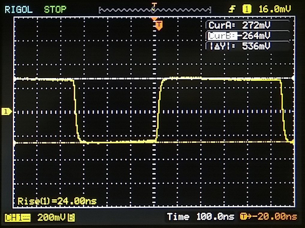 |
| Measurements |
Page Tools
